Oscillating Air Engine
My first term of my Undergraduate, we all were tasked to design and machine an air engine. Introducing, the weebler wobler!
Project Description
As freshmen engineers at George Fox, each student was tasked with building their own oscillating engine, which would run off pressurized air. The main objective was for each student to learn the complete process of engineering from conceptual designs to modeling to actual fabrication and testing. Each student was trying to create an engine that excelled in one of the following criteria: Cost Efficiency, Air Efficiency, Maximum Speed, Maximum Coast, and Maximum Torque. Each engine would have a maximum cost of 32$ and meet other criteria that would define it as an engine.
Poster
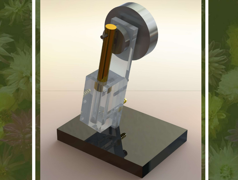
My Engine
I chose to build an engine with Cost Efficiency in mind, meaning that it would have the highest RPM per dollar ratio. My total cost ended up being $5.66, and it reached over 1500 RPMs during the competition.
Some key features Include:
- Mostly Acrylic materials for low cost
- Hollow Piston for reduced weight and bounce
- Angled valve plate for aesthetic purposes
- Vertical piston layout to fit on valve plate
CAD Drawing
Changes Made Throughout the Process
Some major changes I made throughout the process were hollowing out the piston to reduce the amount that the engine bounced around. Another Change I made was machining the cylinder out of acrylic. It was originally going to be made from aluminum, but I changed it for the cost and for the lower weight that acrylic has.
Design Improvements
The biggest change I would make if I were to remake this engine would be to cut a thicker stronger material for the valve plate. It was too weak and would shake while it ran, reinforcing it might reduce this and help it run faster. I also might scale it down a bit, because there isn’t much need for it to be as big as it is, and a smaller engine would be more cost effective.
Skills Learned
Every step of this project was bringing in new concepts, software, and tools to learn and use. From the conceptual side, we learned how to draw quality design sketches using 3 separate viewpoints, orthographic, isometric, and oblique. We also went through all the variables and calculations required to build a working engine. I also learned how to recreate all those drawings and calculations in the 3d CAD software SolidWorks. We lastly learned how to use metal machining tools like the lathe and mill to precisely manufacture our engines. All these tools are extremely useful for future projects and engineering work, and I now have a general understanding of the complete process.