Haptic Smart Dial
I created a haptic smart dial as an embedded systems project.
Project Description
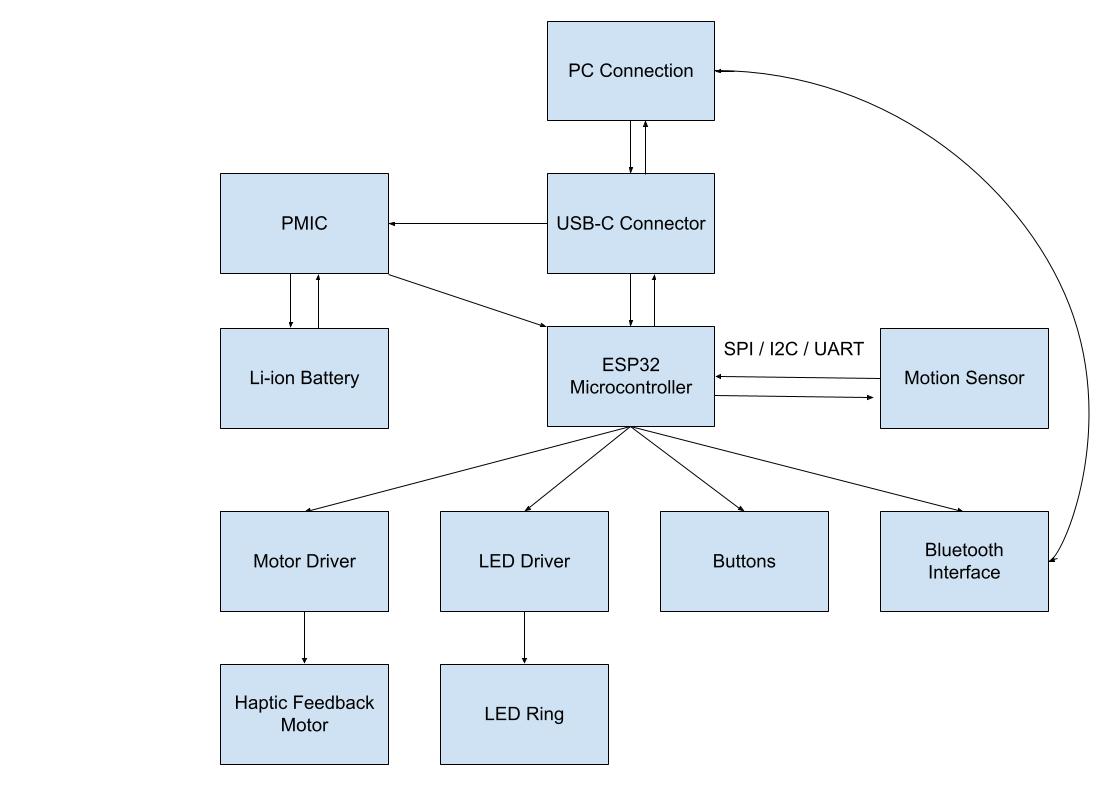
The smart dial is a haptic feedback twisting dial with a screen to connect to a computer system or operate fully standalone. The dial will have wireless and wired capabilities, and power on a lithium battery set into the base. It will be freely spinning on a bearing and also include a vibration motor to provide haptic feedback. The functionality is customizable, but it will include alarm features, computer support for scrolling and browsing documents, and macro functionality to skip songs or adjust volume settings. The embedded system will connect either an ESP32 or Photon 2 micro controller to the power management circuits, motor control modules, screen drivers, and the core functionality of a 14-Bit On-Axis Magnetic Rotary Position Sensor (AS5047P). This IC is going to be a key feature, because it will allow for high resolution tracking of the rotation of the dial. The device is going to be designed to interface like a HID (Human Interface Device) such that a PC will pair via Bluetooth and treat it like a scroll wheel, volume knob, etc depending on the setting.
The key physical features of this device are the high torque 3-phase motor which provides programmable feedback of the turning motion. An LED ring at the top will provide some visual feedback of where the dial is currently engaged to.
The design is still a work in progress, and some implementation details are still being worked out. A couple buttons might be added into the base to allow for a user to actually control the device without a computer. Another design change would be to configure the dial to be a button itself and allow the user to press the entire dial down to engage a small tactile button.
Project Report Document
Block Diagram
Schematic
Bill of Materials
Accomplishments / Failures
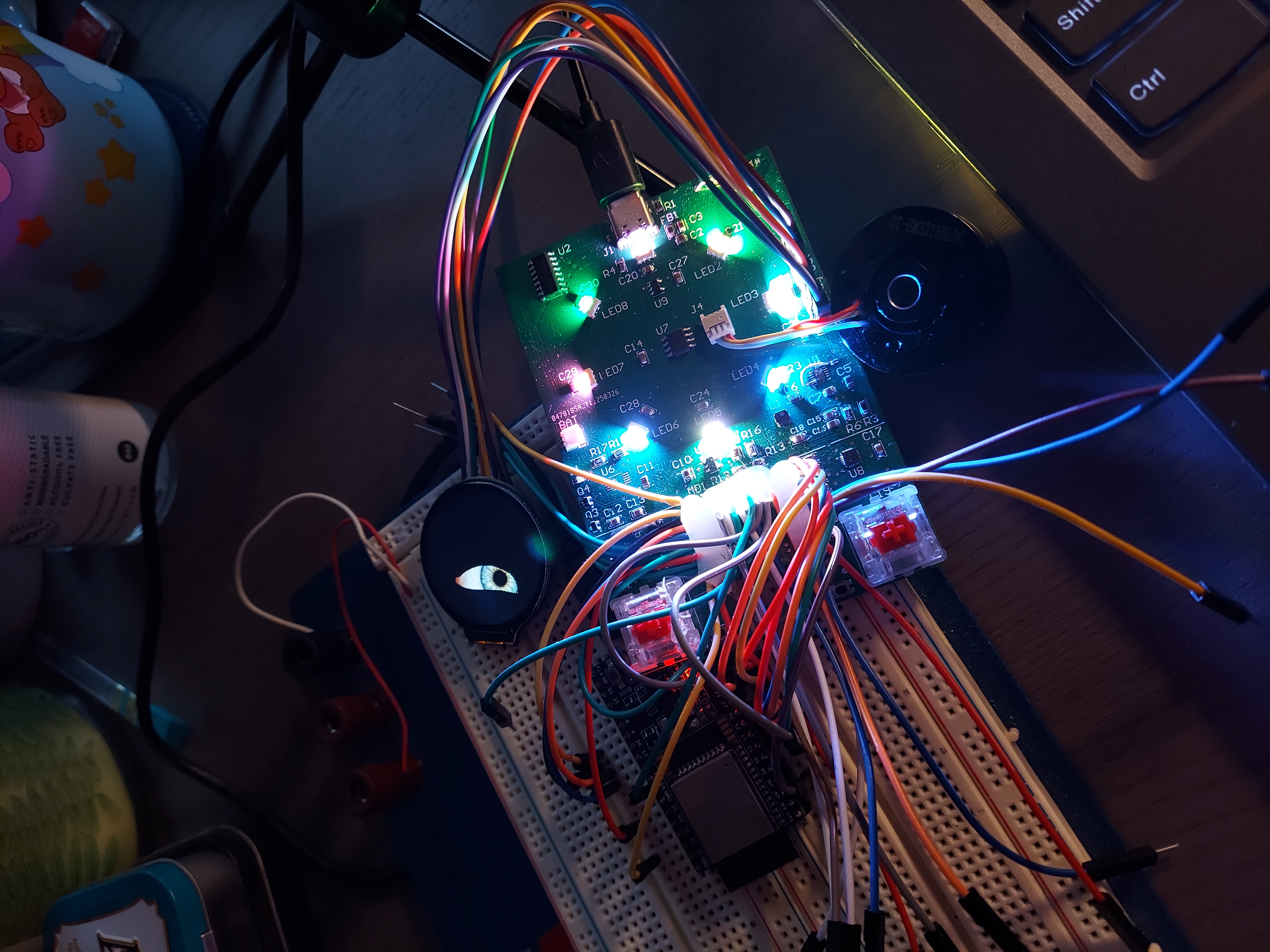
This project was highly ambitious given the amount that needed to be done within a single term. Despite the time constraints and steep learning curves for learning PCB design, power management, and embedded systems programming the final result is something that I would consider by and large to be a successful implementation of my original vision, or at least a good step in that direction. My project covers it all, implementing a full UI with a round LCD, and two mechanical switch buttons. A ring of smart RGB LEDs at the bottom of the dial were also working and displaying brightly at 5V. In fact, the board successfully implemented a 4-layer PCB design with split power planes totaling to 4 separate voltage planes. With thorough measurements, these all operated within a functioning threshold to power each element of the board. This compact design was due to a tight size constraint that I had placed on the project to ensure that the final design would fit in a small case and be easily operated by the end user.
For as many successes and goals reached, there were just as many failures and frustrations in the design. Because of an incorrect boost converter and a missing linear battery charger IC, my goals for making a fully wireless battery powered device that was rechargeable via USB-C was unable to be fully realized. The good thing is that those two chip failures were localized only to the battery voltage plane, and a simple hot wire across the boost converted allowed the entire board to be powered only by USB.
One key feature of my board is that the ESP WROOM32 chip was embedded directly onto the PCB, with all programming logic and serial communication also embedded. Although my computer recognized the board on as COM device, any attempt to actually program the ESP32 via USB failed. Normally this would be a full stop for the project, no programming means no working board, but the show must go on. I removed the micro controller chip from the board and hot wired an ESP32 development board to be able to program the main PCB.
Lastly, several integral sensors and drivers ultimately weren’t able to be diagnosed and implemented. The magnetic position sensor was signaling that it was getting valid data back through serial communication, but no actual values were being measured on the SDA line. Similarly, firmware was flashed to the motor driver module, but the motor did not move. I am not sure if it was software or hardware issues, but as of the finalization of this project those key features were not working.